

R&D
Research & Development
Software applications
The design/process/manufacture path, which consists of taking an idea from concept to product, is one that ELETTRONICA CONDUTTORI engineers must understand first-hand. Every step of this process uses computers : design analysis, machine control, quality assurance and market analysis.
Engineers are also involved to develop and implement user-friendly and reusable computer solutions. Readability, reliability and documentation are stressed in the development of programs.
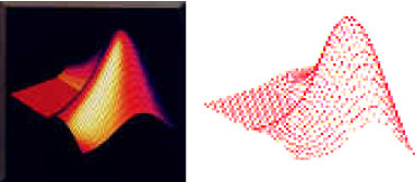
To accomplish these aspects, ELETTRONICA CONDUTTORI engineers employ MATLAB as main technical computing environment.
Through the OS-independent MATLAB language, ELETTRONICA CONDUTTORI engineers are able to write portable code easily, with key advantages as:
- Software life cycle
- Maintenance
- Modularity
- Abstraction
- Software prototypes
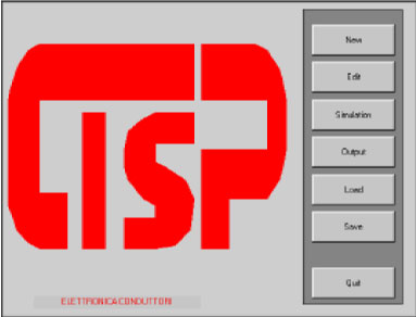
The most typical MATLAB code, developed by ELETTRONICA CONDUTTORI engineers, is CISP (Cable Interference Simulation Program), finalised to demonstrate the Shielding Effectiveness (SE) of the ELETTRONICA CONDUTTORI shielded signal cables.
CISP is a computer aided approach to cable behaviour from the electromagnetic interference hardening point of view. With the CISP program is possible to evaluate all the significant electrical/structural parameters needed to meet the STI (Surface Transfer Impedance) requirements.
In the ELETTRONICA CONDUTTORI CISP code most effects have been put for the following purposes :
- Establish an analysis method slanted towards the development of the STI test, in order to determine the SE behaviour of the CUT (Cable Under Test) that occurs in the measurement
- Implement the method into a code in order to evaluate all the needed design parameters
- Provide an optimisation algorithm of the cable braid design parameters to be selected during the design development activity
The optimisation routine generates:
- A close grid of values with the STI function expanded in the relative Taylor series in order to define the combination of values in a minimum computational time
- A loop on a single variable for all design variables, while for other ones remain fixed
Publications
A Fast, Accurate, and Sensitive Method for Calculating Surface Transfer Impedance
PDF document written by :
F. Calluso (Politecnico di Torino C.so Duca degli Abruzzi)
M. Casti (Università di Torino – Istituto di Fisica)
G. Ferrero (ALENIA DIFESA, St. Pr. Aeroporto)
L. Zanero (ELETTRONICA CONDUTTORI)
About a fast, accurate and sensitive method to calcolate the transfer impedance of the surface.
Technical details
This Web section presents the technical characteristics of the main cables produced by ELETTRONICA CONDUTTORI.
The section is constantly updated according to the news or production changes and has the fundamental purpose of operating as a real technical catalog at the customer’s service.
The section currently lists the peculiar characteristics of the cables produced.
ELETTRONICA CONDUTTORI intends to make available in this section in a short time the complete catalog, with the detailed technical characteristics of all the products. We therefore remind you, in this regard, that if the Customer needs further information, he can always use the specific “Contact us” form, which the ELECTRONIC CONDUCTORS staff will promptly fulfill.
Materials for primary insulation and secondary coating (sheaths).
Primary Insulation
Cables with primary insulation in polyvinyl chloride (PVC)
PVC is the most commonly used material for primary insulation in cables for security and alarm systems, electronics, automotive, automation, power supply, signaling and control of equipment and machine tools and industrial.
It is a decidedly versatile material that allows to satisfy multiple and different needs.
Its characteristic operating temperature can range from 70 ° C to 125 ° C, depending on the different formulation of the compound used. The addition of special additives and plasticizers increases the compound’s resistance to high temperatures.
Thanks to the decades of experience gained ELETTRONICA CONDUTTORI is able to recommend the type of PVC most suitable for the application requested by the customer.
In particular, in the event of a request to pass the non-fire propagation tests according to CEI 20-22 / 2, CEI 20-22 / 3, IEC 332.3A, IEC 332.3C, special PVC with a higher oxygen index.
Furthermore, upon request, the PVC used can also be supplied lead-free. All PVC compounds, with electrical and mechanical properties that comply with CEI 20-11, CEI 20-14, CEI 20-20, HD 21.1 standards, are purchased from qualified and certified suppliers.
Cables with primary insulation in polyethylene (PE)
Polyethylene (PE) is the most commonly used material for primary insulation of radio frequency coaxial cables.
Thanks to its low dielectric constant (er = 2.3), it allows the creation of low-capacity cables, with a signal transmission speed that can even reach 0.8c (c = light speed) in the case of cellular polyethylene. Furthermore, the dielectric constant and the loss factor are largely independent of temperature and frequency.
All polyethylene compounds are purchased from qualified and certified suppliers and, upon request, their electrical and mechanical characteristics meet the standards ASTM D 1248 type II, DIN VDE 0207 2YI1, 2YI3, IEC 708.
Cables with primary insulation in cross-linked polyethylene (XLPE: cross-linked polyethylene)
Cross-linked polyethylene (XLPE) is used for the primary insulation of low, medium and high voltage cables, for signaling and control cables.
The cross-linking process improves its resistance to stress cracking and resistance to cold. Since XLPE does not melt like an elastomer, it is capable of withstanding thermal loads of up to 120 ° C.
Also in this case the polyethylene compounds are purchased from qualified and certified suppliers, with electrical and mechanical characteristics that comply with CEI 20-11 E4I, ASTM D 1248 type I, DIN 57 207 / VDE 0207 2XI1, IEC 502, IEC 754- 2.
Polypropylene (PP) primary insulation cables
Polypropylene (PP) is used for the primary insulation of cables for telecommunications, telephony, data transmission.
Thanks to its low dielectric constant (er = 2.3), it allows the creation of low-capacity cables with a signal transmission speed that can reach up to 75-80% of the speed of light (cellular polypropylene).
Furthermore, the dielectric constant and the loss factor are largely independent of temperature and frequency.
Compared to polyethylene, polypropylene is more rigid.
Cables with primary insulation in thermoplastic rubber (TPE-O)
Thermoplastic rubber (TPE-O) is used for primary insulation in cables for electronics, automotive, power supply of equipment and machine tools and industrial, signaling and control, and combines the performance of vulcanized rubbers, such as heat resistance and low deformations , the ease of transformation of thermoplastic materials.
It is particularly used as primary insulation for spiral and extendable cables, in particular in the automation sector where flexibility is a fundamental requirement.
All thermoplastic rubbers are purchased from qualified and certified suppliers; moreover, upon request, it is possible to use materials included in the UL Yellow cards and in the UL 62 for flexible cord applications bulletin.
Cables with primary insulation in polyester-based thermoplastic elastomer (TPE-E)
Polyester (TPE-E) is used for primary insulation in cables for electronics, automotive, power supply of equipment and machine tools and industrial, signaling and control when excellent resistance to fatigue due to bending, abrasion and impact are required even at very low temperatures, at temperature peaks, chemical and atmospheric agents.
It is particularly used as primary insulation for spiral and extensible cables and in the automation sector.
Suppliers are qualified and certified and the materials used are included in the UL Yellow cards.
Cables with flame retardant primary insulation, halogen-free, with low development of toxic and corrosive fumes and gases
It is used as primary insulation in cables for security and alarm systems, electronics, equipment power supply, signaling and control.
It is particularly used for cables installed in public buildings (hospitals, theaters, airports, subways) where in the event of a fire, the basic requirements are non-propagation and low emission of opaque, harmful and corrosive fumes, thus ensuring the visibility of escape routes.
Secondary coating (sheaths)
- polyvinyl chloride (PVC)
- thermoplastic rubber (TPE-O)
- polyester based thermoplastic elastomer (TPE-E)
Polyethylene is used as a secondary coating for cables when installation outdoors or in wet environments is required; in fact this material has excellent properties of resistance to water and saline solutions.
It is particularly used for spiral and extensible cables, in the automation, automotive, electronics cables, geophysical research, power supply of equipment and machine tools and industrial sectors, signaling and control when excellent resistance to bending fatigue, abrasion, impact even at very low temperatures, chemical and atmospheric agents.
All ELETTRONICA CONDUTTORI polyurethanes are purchased from qualified and certified suppliers and, on request, we can use materials:
-
inserted in UL Yellow cards and which meet the requirements of DIN VDE 0282 part10
- halogen-free flame retardants (classified V0 according to UL 94)
Conduttori
The material used is mainly bare (bare copper) or tinned copper.
The tinned type is recommended when weldability is required in the shortest possible time.
The conductors used can be of the single wire type (solid conductors), strands (bunched stranded conductors), concentric (concentric stranded conductors), concentric unilay (concentric unilay stranded conductors) and of different flexibility depending on the application required.
The conductors used meet the requirements of CEI 20-29, CENELEC HD 383 S2, IEC 228, VDE 0295 and can be supplied in the different classes of flexibility required.
For more information, see the tables relating to conductor training.
Structural types of shielding
The types of shielding used allow different solutions:
- aluminuim/polyester tape shield
- braided copper shield
- spiral copper shield
- aluminium/polyester tape/braided copper composite shield
- aliminium tape/spiral copper composite shield
- double braided shield
| Type | Material | Working Temperature (°C) | Density (g/cm3) | Halogen content (%) | Dieletric constant (1MHz) | Dieletrictric strenght (KV/mm) |
|---|---|---|---|---|---|---|
| PVC |
polyvinylchloride
|
15 ÷ 90 | 1.25/1.50 | 35 | 4.5 | >12 |
| PVC (spec.) | polyvinylchloride | -40 ÷ 125 | 1.25/1.50 | 35 | 4.5 | >12 |
| PE | polyethylene | -50 ÷ 80 | 0.92/0.96 | 0 | 2.3 | >22 |
| XLPE | x linked polyethylene | -60 ÷ 120 | 0.91/0.92 | 0 | 2.3 | >22 |
| PP | polypropylene | 40 ÷ 105 | 0.90 | 0 | 2.3 | >22 |
| TPE-O | termoplastic rubber | -40 ÷ 125 | 0.95/0.98 | 0 | 2.7 | >20 |
| TPE-E | termoplastic elastomer | -40 ÷ 105 | 1.20/1.25 | 0 | 3.8 | >16 |
| TPE-U | polyurethane | -40 ÷ 90 | 1.12 | 0 | – | >10 |
| TPE-U (spec.) | polyurethane | -40 ÷ 105 | 1.12 | 0 | – | >10 |
Cable shielding
The connecting cables between devices and their connectors are the preferred route by which electromagnetic interference propagates in the external environment and by which, from the outside, it couples to the electrical conductors that exchange signals between the devices of the system, thus creating situations of susceptibility.
It should be remembered that cabling is an area of uncertain responsability; it is never clear who should choose the cables, their route, or their location inside the system. Therefore it may happen that an apparatus is designed perfectly from the EMC point of view, but that the choice of the connecting cables between the apparatus itself and the outside world is not made with equal care. Thus, the apparatus-cable whole may not pass the tests of EMC. There are essentially three mechanisms by which phenomena of emission and susceptibility manifest themselves in electrical connections:
- radiated emission from cables, which act as transmitting antennae;
- radiation susceptibility of the cables, which act as receiving antennae;
- electric and/or magnetic coupling between cables.
In the control of interfering emission the principle of reciprocity rules, in the sense that what is done to a cable to reduce radiated emission is also valid for increasing its resistance to radiation susceptibility.
As far as cable screens are concerned, it must be remembered that their effectiveness depends on the value of the SE of the cable braid and on the way in which the screens are terminated. From the termination of cable screens point of view, connectors come into play; these are an indispensable means of connection between cables and devices.
Only recently has the great difflculty of seeing cables and connectors as two separate entities been overcome and have they begun to be considered as one. In the literature there exist many studies aimed at verifying and quantifying the effect of the connection of a cable screen to the chassis ground of an apparatus (the so-called pigtail); everyone agrees on the criticality of this element with regard to screening efficiency and radiation.
In any case the influence of the type of connector starts to make itself felt at a few MHz, or the frequency at which the length of the cable is equal to a tenth of a wavelength.
Overlooking the cable contribution to the system EMC performance can ruin the effect of the best system shielding. In fact, cable shielding very often is the weakest link in the overall system shielding.
For a given frequency, the key contributors to the overall performance of a shield placed upon a cable are :
- shield material
- termination method (clamp, solder, pigtail, type of connector)
- geometry of the installation (cable lenght, cable height, orientation vs. the field pointing vector, type of conductive ground)
In the final analysis, each of these contributors behaves differently, depending on the nature of the field : near E-field, near H-field or far field.
SHIELD MATERIAL AND THICKNESS VS. THE TYPE OF EMI
A cable shield can be made of a thin aluminum film flashed over a paper or mylar substrate, a copper braid, a thinly wrapped metal foil, a corrugated pipe. All these material have basic shielding properties which depend on two mechanisms reflection and absorption.
Reflection is a radiated phenomenon and is the result of the mismatch between the impinging wave impedance and the shield barrier impedance.
Absorption depends on the skin effect. At frequencies high enough for the skin effect to occur, absorption becomes significant. If the shield is a solid tube, this absorption will increase exponentially. If the shield is a braid, all the minuscule rhombic aperture due to the weave of copper wires will spoil the absorption effect by making the shield more and more trasparent as frequency increases. Depending on the optical coverage, this effect can show up as low as 1 to 10 MHz, ruining the Shielding Effectiveness (SE) of the braid.
SHIELD TERMINATION
Where and how the shield is terminated can radically affect the performance of a shield. Once a cable shield is mounted, its termination may be the weakest link in the chain, especially at higher frequencies. As a first approximation, the quality of a shield can be associated to its DC sheath resistence, altough this statement becomes invalid above the HF region. Since it is very difficult to have the shield terminated by a connector clamp or pigtail whose impedance is much less than the shield material impedance, the termination hardware is always the limiting factor of the in situ performance.
For example, a braid shield resistance of a 0.75 m piece of shielded cable, with a braid resistance of 3 mohm/m is equal to 2.25 mohm. A typical bonding resistance of the braid to the serrated clamp is 0.5 mohm. An ordinary hand-tightened connector shall exhibits a contact resistance of about 3 mohm to the receptacle. Finally, the contact resistance of the connector socket flange to the rack wall, assuming it is normally tool tightened using four screws, is again 0.5 mohm.
Since there are two ends to this cable, the total termination resistance is :
Rterm = 2 (0.5 + 3 + 0.5) = 8 mohm > 2.25 mohm of the braid shield resistance
The termination contribution to the whole shield resistance will be more than three times that of the braid alone. Not only can an improper shield termination spoil the cable shield efficiency, it can be the source of secondary mechanism which can cause more EMI than if there were no shield at all.
The key for preventing or solving such problems is always the same : identify any existing EMI current paths.
OVERALL GEOMETRY OF THE INSTALLED CABLE
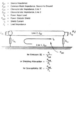
The screen of a cable can be seen as the conjunction of two transmission lines, with the screen being the transfer medium between them. The two circuit models are:
- The internal circuit 2 has well controlled parameters such as the source impedances Zg and load Zl, and characteristic impedance Z02. These parameters define the current and voltage values at each point in the circuit, including the effects of reflection and standing wave
- The external circuit 1 has very poorly controllable parameters, since each of the termination impedances Zg1 and Zg2 can vary from 0 to infinite, depending on the grounding conditions, and its characteristic impedance Z01 depends on the h / D ratio, i.e. the cable height above the ground plane with respect to the cable diameter.
The efficiency of a screen is in fact the measure of the percentage of energy transferred from circuit 2 to circuit 1 in the case of EMI emission, or transferred from circuit 1 to 2 in the case of susceptibility.
The characteristic impedance of circuit 1 has a significant effect on this energy transfer, especially at multiple values of heath / 4.
Therefore, for a given screen installed, with certain terminations there will be different behaviors, depending on its length and its height above its ground plane.
UNBALANCED VS. BALANCED SHIELDED CABLES
DEFINITION OF SE FOR CABLE SHIELD
The basic definition of SE is :
SE(dB) = 20 log [Vinduced without shield / Vinduced with shield ]
The shield termination method strongly influences the result and can even totally obscure the parameter being measured, i.e., the quality of the shield alone.
Because of these problems, another measure of the shield quality, the shield surface transfer impedance ZT is preferred. It provides a figure of merit which is an absolute parameter, instead of being a relative term like SE. Also, the measurement of ZT is relatively easy to perform.
TRANSFER IMPEDANCE OF COAXIAL CABLE SHIELDS
To define the quality of a cable in the EMC sense, the concept of surface transfer impedance has been introduced. Consider figure, where we show the screen of a cable in which a surface current Is flows and let DV be the voltage drop that is generated inside the cable over a length ,DX.
Then the surface transfer impedance Zt is defined as: < Zt = ΔV / (Is· Δx) (ohm / m) Below about 100 KHz, Zt is practically equal to the shield DC resistance.
The transfer impedance will consist of two components :
- penetration component representing the energy diffusion through the metal of the screen
- coupling component representing the H field diffusion through the rhombus-shaped holes
The complete Zt for the braided wire shield can be written :
Zt = RDC + jwM12
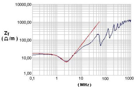
At very low frequency, the STI is equal to the direct current resistance of the braid.
With increasing frequency, two effects will occur :
- due to the skin effect the STI will drop
- due to the H field coupling through the braid structure there will be a rise of the STI proportional to the frequency
Coaxial cables
The correct selection of cable requires proper analysis of the electrical, physical and electromagnetic parameters of the system employing the cable to be selected.
To assist you in this analysis, our web site includes some reference data, enabling you to determine the characteristics of the cables presently available and also to evaluate how they may vary under physical operating conditions. First, review the Application Notes to determine all of the cable characteristics which must be considered. Then from the list of EC standard cables, select those which will best meet your requirements.
In choosing the appropriate cable construction for a particular application, the most important cable characteristics to be considered are the following :
- Characteristic impedance [Z0]
- VSWR
- Capacitance [C]
- Inductance [L]
- Cw power rating
- Max operating voltage
- Attenuation
- Velocity of propagation
- Shielding effectiveness
- Cut-off frequency
- Flexibility
It should be noted that the stipulation of materials and dimensions does not guarantee that each lot of cable will have identical mechanical or electrical characteristics. Different types of manufacturing equipment or different manufacturing conditions can give substantially different performance characteristics.
| Capacitance | C = 6.28 ε / ln (D/d) | (pF/ft) |
| Inductance | L = 0.16 μ / ln (D/d) | (mH/ft) |
| Characteristic impedance | Z0 = ( 138 / √ εr ) log (D/d) | (ohms) |
| Velocity of propagation (% di c)fc | V = 100 / √ εr |
where:
- d = outside diameter of inner conductor in inches
- D = inside diameter of outer conductor in inches
- c = velocity of light
- ε = ε0εr = the relative dielectric constant of the insulation of the cable
- μ = μ0μr = permeabilità magnetica dell’isolamento del cavo
Characteristic impedance
The most common values for coaxial cables are 50, 75 and 95 ohm. Other impedances from 35 to 185 ohm are available in the coaxial configuration. The VSWR (Voltage Standing Wave Ratio) of a particular length of cable is an indicator of the difference between the actual input impedance of the cable and its average characteristic impedance
Impedance (VSWR) uniformity
IThe VSWR of a cable assembly is the summation of reflections due to the connectors, the connector termination technique and the cable. The VSWR of the cable is the summation of random and periodic reflections within the cable, most commonly caused by variations within the processing equipment. The VSWR will vary with frequency. If required, cables can be procured in specified lenghts to a max VSWR requirement on a swept basis. If a very low VSWR is required, it may be necessary to procure complete assembly verified on a swept basis.
Capacitance
Capacitance values (shown below) for standard coaxial lines depend on cable geometrical parameters and dielectric material. Typical values for a few cables are the following :
| Nominal capacitance | Cables types |
|---|---|
| 30.8 | 50 Ohm – Solid Polyethylene |
| 29.4 | 50 Ohm – Solid PTFE |
| 20.6 | 75 Ohm – Solid Polyethylene |
| 19.5 | 75 Ohm – Solid PTFE |
Velocity of propagation
The velocity of propagation of cable is determined primarly by dieletric constant of the insulating material between the conductors. This property is usually expressed as a % of the velocity of light in free space.
Average CW power rating
High ambient temperature and high altitude reduce the power rating of a cable by impeding the heat transfer out of the cable. VSWR reduces power rating by causing hot spots. To select the cable construction for a particular requirement, determine the average input power at the highest frequency from system requirements. Then determine the effective average input power as follows:
Temperature and altitude corrections are tabulated on available data sheet.
VSWR correction factor = ½ (VSWR+1/VSWR) + ½ K1(VSWR-1/VSWR)
Maximum operating voltage
A cable cannot operate continuously with corona which causes noise generation, dielectric damage and eventual breakdown. The maximum operating voltage must be less than the corona level of the cable. This should not be confused with the dielectric strength of the cabie, which is a test voltage which is applied for one minute only during manufacture.
The max permissible DC (rms) voltage level is conservatively 3 times the AC level.
To select a cable for a particular application, determine the actual rms or peak voltage from system requirements. Then apply : Effect. voltage = (actual voltage x Ö VSWR)
PROPERTIES OF WIRE AND CABLE INSULATING MATERIALS
| Material | Dielectric Costant | Power Factor | Normal operating Temperature limits (°C) |
|---|---|---|---|
| TFE | 2.1 | 0.0003 | -75 ÷ 250 |
| Polyethylene | 2.3 | 00003 | -75 ÷ 80 |
| Nylon | 4.60 ÷ 3.5 | 0.04 ÷ 0.03 | -60 ÷ 120 |
| PTFE | 1.5 | 0.0002 | -75 ÷ 250 |